Spring Constant Units Calculator
Spring Constant Units
Attention! Input results shown will be +/- 10% from middle value. Hint: The closer your min and max inputs are, the more accurate your results will be!
Table of contents
- Definition of Spring Constant Units
- Units of Measurement for Spring Constant
- Precision in Spring Constant Calculations
- Calculating Compression and Extension Spring Constants Units
- Formula A for Basic Spring Constant Calculation
- Advanced Calculations with Formula B
- Torsion Spring Constant Calculations
- Principles of Torsion Spring Mechanics
- Leverage Professional Tools for Enhanced Spring Design
Definition of Spring Constant Units:
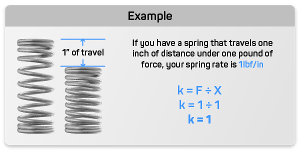
Spring constant units are the unit of measure for spring force meaning the spring force is measured in either pounds per inch or newtons per millimeter of distance traveled for compression and extension springs. For torsion springs the spring constant units are in inch pounds per degree or Newton per millimeters per degree of radial force meaning the twisting of the springs legs in a clockwise or counterclockwise radial motion. This key parameter dictates how much force is needed to compress for compression springs, extend for extension springs or rotate for torsion springs by a given distance, directly influencing the behavior and efficiency of the mechanical system it is part of.
Units of Measurement for Spring Constant
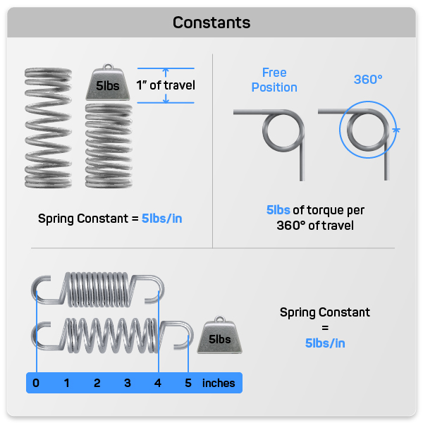
- Compression and Extension Springs: For these types of springs, the spring constant units is typically measured in pounds of force per inch (lbf/in) in the English system. This unit indicates how many pounds of force are required to compress or extend the spring by one inch. In the metric system, the equivalent measurement is newtons per millimeter (N/mm), indicating the force in newtons required to achieve a millimeter of displacement.
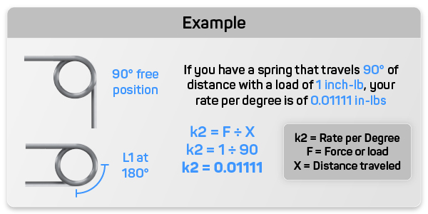
- Torsion Springs: The spring constant units for torsion springs is measured in terms of torque, specifically inch-pounds of torque per degree or per 360 degrees in the English system. This tells us how much torque is needed to twist the spring by one degree or a full revolution (360 degrees). The metric counterparts are newtons per millimeter per degree or per 360 degrees, providing a measurement of torque per angular displacement in the metric system.
Precision in Spring Constant Calculations
Accurate measurement and calculation of the spring constant units are crucial for the successful application of springs in mechanical systems. The spring constant unit determines how a spring will behave under load, affecting everything from mechanical durability to user experience. For designers and engineers, calculating the correct spring constant unit is fundamental to ensuring that a spring can meet the operational demands placed upon it without failure.
Calculating Compression and Extension Spring Constants Units
Compression and extension springs are vital components in mechanical systems, requiring precise calculations of their spring constants to ensure optimal performance. The spring constant, denoted as k, quantifies the force necessary for a specific displacement of the spring, essentially defining the stiffness of the spring.
Key Parameters in Spring Constant Calculations
- Force (F): This is the load applied to the spring, measured in pounds of force (lbf) or newtons (N).
- Distance Traveled (X): This refers to the displacement of the spring under load, measured in inches (in) or millimeters (mm).
- Spring Constant (k): The outcome of the calculation, representing the ratio of force to displacement, providing a measure of the spring's stiffness.
Formula A for Basic Spring Constant Calculation
For a straightforward approach to determining the spring constant, use the following formula:
k = F ÷ X
This formula is particularly useful for quick estimations or when working with simple spring configurations where precision is less critical.
Application Example: Calculating the spring constant for a micro switch. Suppose a designer needs to ensure that a micro switch compresses 1.256 inches under a load of 0.500 lbf to provide a comfortable movement. Using the formula, the spring constant k would be calculated as k = 0.500 lbf ÷ 1.256 in = 0.398 lbf/in. This calculation helps in selecting the right spring, in this case we’re using access springs part number PC071-2062-14300-HD-5500-C-N-IN, which balances the micro switches load support more evenly..
Advanced Calculations with Formula B
For more complex or precision-critical applications, a detailed understanding of the spring's physical properties and geometry is necessary. This includes:
- Wire Diameter (d): The thickness of the spring wire, a critical factor as it directly influences the spring's stiffness.
- Outer Diameter and Mean Diameter (D): These dimensions impact the overall stress distribution and mechanical behavior of the spring under load.
- Material Properties (E and G): Young’s Modulus (E) and Shear Modulus (G) describe the material’s response to elastic deformation.
- Number of Active Coils (n): This affects how the load is distributed across the spring.
- Poisson’s Ratio (v): This material property affects the lateral expansion or contraction under load.
The enhanced formula for a more precise calculation is:
k = Gd^4 ÷ (8D^3 * n)
This formula takes into account the material’s shear modulus and the geometric factors of the spring, providing a highly accurate calculation for the spring constant.
Application Example: Imagine you are designing a suspension system for a lightweight robotic arm. This system requires a spring that can both compress and extend to absorb shocks and provide smooth operation. You decide to use a spring with the following specifications:
Part Number |
PC109-1000-12000-MW-3000-CG-N-IN |
Wire Diameter (WD) |
0.109 inches |
Outer Diameter (OD) |
1 inch |
Material Type |
Music Wire (11.5×10^6 psi) |
Active Coils (n) |
10 |
Step-by-Step Calculation:
Calculate the Mean Coil Diameter:
Mean coil diameter D is the outer diameter minus the wire diameter:
D = OD − WD
D = 1 − 0.109
D = 0.891 inches
Compute d^4 and D^33:
d^4 = (0.109)^4 = 0.000141 (approximately)
D^3 = (0.891)^3 =0.707 (approximately)
Substituting and Solving
k = (11.5×10^6) × 0.000141 ÷ 8 × 0.707 × 10
k = 1615.5 ÷ 56.56
k ≈ 28.669 pounds per inch
This means the spring rate k is approximately 28.669 pounds per inch.
Practical Application
1. Spring Selection for a Mechanical Device:
- Design Scenario: In the design of a mechanical device, the spring must compress by 1.5 inches under a specific force.
- Given Requirements: The force needed to compress the spring by 1.5 inches can be calculated using Hooke's Law:
F = k × x
Where:
- F is the force applied (in pounds),
- k is the spring rate (28.669 pounds per inch),
- x is the displacement (1.5 inches).
F = 28.669 pounds per inch × 1.5 inches
F = 43.00 pounds
The required force to compress the spring by 1.5 inches is approximately 43.00 pounds.
Torsion Spring Constant Calculations
Torsion springs are designed to exert torque or rotational force by twisting the torsion springs legs radially. These springs are pivotal in applications where angular motion is required, such as door hinges, trailer ramps, and mechanical levers. Accurately calculating the torsion spring constant units is critical for ensuring the functionality and longevity of mechanisms that rely on these springs.
Principles of Torsion Spring Mechanics
The torsion spring constant, also referred to as the rate of torsion or torque per degree of rotation, defines the stiffness of a torsion spring. It tells us how much torque will cause the torsion spring to rotate one degree. The specific characteristics of a torsion spring's constant include:
- Units of Measurement: Typically measured in inch-pounds of torque per degree or newtons per millimeter per degree, these units describe the torque required to achieve a one-degree of rotation.
- Importance in Design: This constant determines the response of the spring to applied torque, influencing how well a spring can return to its original position without deforming.
Formula A: Calculating Torsion Spring Rate per 360 Degrees
For initial calculations or general applications, the spring rate for a complete 360-degree rotation can be estimated with:
R = Ed^4 ÷ 10.8 × D × N
Where:
- E is the Modulus of Elasticity, reflecting the material’s resistance to deformation.
- d is the wire diameter.
- D is the mean diameter of the spring.
- N is the number of active coils.
This formula provides the basic rate, which can be divided by 360 to find the rate per degree:
R2 = R ÷ 360
Application Example: Suppose you are designing a precision spring for a small-scale device, such as a miniature electronic component or a delicate mechanical system. The torsion spring needs to be capable of providing a specific resistance to rotational movement. You decide to use a torsion spring with the following specifications:
Part Number |
PT047-500-3000-MW-LH-0785-N-IN |
Wire Diameter | 0.047 inches |
Outer Diameter | 0.5 inches |
Material Type | Music Wire |
Total Coils | 3 |
Calculation:
Mean coil diameter D is the outer diameter minus the wire diameter:
D = OD − d
D = 0.5 − 0.047
D = 0.453 inches
Substitute the Values into the Formula:
- E = 30 × 10^6 psi
- d = 0.047d inches
- D=0.453 inches
- N=3
R = (30×10^6) ×(0.047)^4 / 10.8 × 0.453 × 3
Compute d^4 and 10.8 × D × N:
d^4 = (0.047)^4 =4.86 × 10⁻⁶ (approximately))
10.8 × D × N = 10.8 × 0.453 × 3 =14.99
Calculate the Spring Resistance:
R = 30 × 10^6 × 4.86 × 10^−6 / 14.99
R = 145.8 / 14.99
R ≈ 9.72 inch-lbs / per 360 degrees
9.72 / 360 = 0.027 inch-lbs per degree of Rate
Formula B: More Precise Calculation per Degree
When precision is crucial, especially in high-performance applications where exact torque measurements are necessary, the torsion spring rate per degree can be calculated directly:
k2 = F ÷ X
In this context:
- F represents the torque or load applied.
- X is the angle of twist in degrees.
- This direct approach allows for precise adjustments to spring design to meet specific torque requirements, ensuring the spring functions correctly under load.
Leverage Professional Tools for Enhanced Spring Design
To ensure that your spring designs meet the exacting demands of your specific applications, consider utilizing professional tools and resources like Acxess Spring's Online Spring Force Tester and Spring Creator 5.0. These platforms offer advanced features that simplify the calculation process, provide visualizations of spring behavior under load, and allow for rapid iteration on design parameters.
Engineers, designers, and manufacturers are encouraged to integrate these tools into their design processes to enhance the accuracy of their spring constant units calculations and the overall quality of their mechanical components. Whether you are in the initial stages of product development or looking to refine existing designs, Acxess Spring's tools can provide the precision and efficiency you need.
Explore these tools today to see how they can improve your design workflow and help you create more reliable and effective spring-loaded systems. Visit Acxess Spring to learn more about their innovative solutions and start optimizing your spring designs for better performance and reliability.
Created by Luis Enrique Rayas
Spring Designer in Spring Calculation at Acxess Spring